All Categories

UAV NAVIGATION AMPLIFIER

All Categorys

UAV Navigation Amplifier
UAV Communication Amplifier
Broadband Amplifier
General RF Amplifier
Pulse SSPA
Linear RF Amplifier
SDR(Software Defined Radio)
Amplifier Design Request

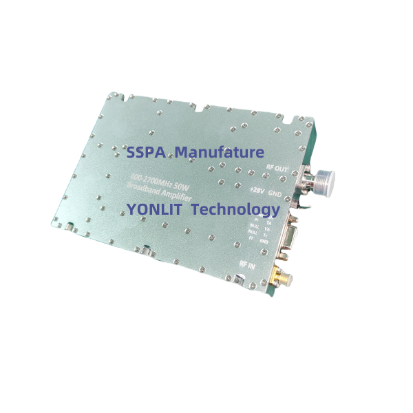
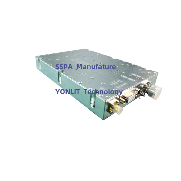
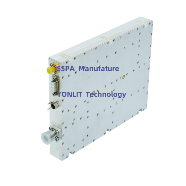
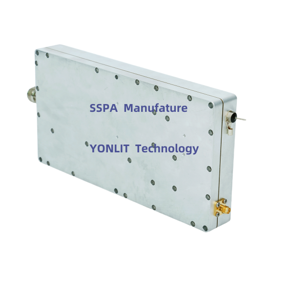
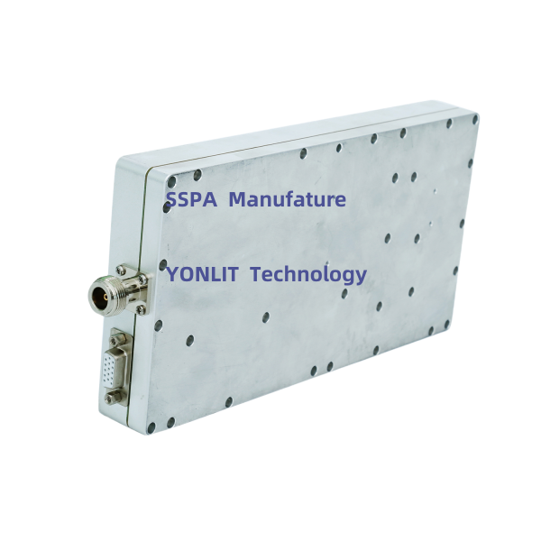
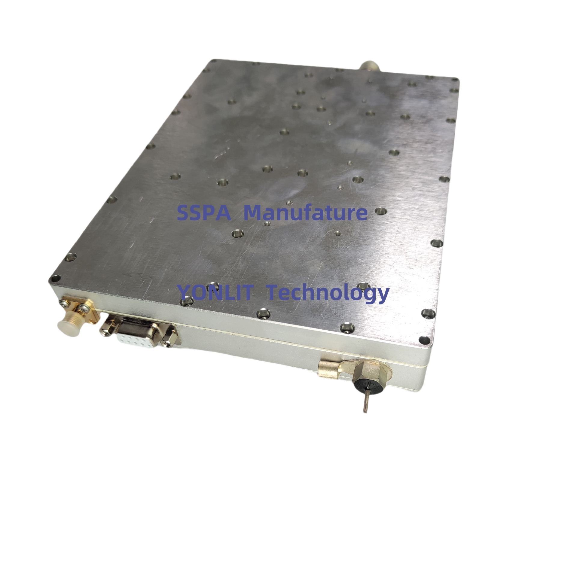
1.1-1.6GHz 45W Amplifier

Frequency: 1150-1620MHz
Pout: >35W
Modulation Type: CW/FM/AM
Working Voltage: 28VDC

Place of Origin:

Shenzhen, China

Brand Name:

YONLIT, OEM,ODM

Model Number:

HPG45(1150-1620MHz)

Main Application: Goverment vehicle communication, Electronic warfare, electronic countermeasure, anti drone, counter UAV, Military vehicle communication, Anti satellite navigation. SDR, Amplify satellite navigation signals: GPS L1,L2, L4,L5;  BDS;  GALILEO L1 L5; GLONASS L1,L5.


Key specification:

Pout >50W at any frequency in 1150-1620GHz

Pout  >50W from -25℃ to 80℃


Description

  • Pout>50W from -25℃ to 80℃
  • Pout >50W at any frequency  in working frequency band
  • LDMOS Device  ensure high efficiency and ultra broadband.
  • Continuous wave output  suitable for  CW ,FM or AM modulation
  • ALC control function of output power  or working current
  •  Over-high VSWR to avoid or reduce the damage from any mismatch
  • Protection  over  short or open of output port
  • Pout and Gain of Temperature  compensation
  •  Over-high temperature protection, Shutdown more than 75℃, auto-restart less than 50 ℃.

Competitive Advantage:

  • Output Power is stable 50dBm±0.5dB over full temperature range (-25℃ to 80℃) at same Frequency
  • Output Power is stable 50dBm±0.5dB over full working Frequency band at same temperature
  • LDMOS Device ensure low Spurious emission and low Harmonics emission,
  • Continuous wave output is suitable for CW ,FM or AM modulation
  • 31dB attenuation is easy to control gain and Pout
  • ALC (Auto Level Control) ensure high P1dB and high IP3.
  • Select ROGERS Rogers high-frequency printed circuit board (PCB) to ensure stability of Amplifier modules
  • All screws are made of stainless steel, the amplifier modules are corrosion-resistant
  • All of devices are new (including final RF power Amplifier),that assure high quality of modules
  • Isolator is embedded in amplifier modules at output port,  good VSWR and protect PA from damage.
  • Coupling SMA port of output power are accurate -40dB ± 1dB,easy for monitoring
  • With logarithmic RF Power detector, detector output of forward power and reversed power is linear-in-decibels.   
  • ALC control function with output power or working current
  • Protection over High VSWR and shutdown

* Over-high VSWR to avoid or reduce the damage from any mismatch

  • High Temperature Protection and re-start when temperature low down.

* Over-high temperature protection, Shutdown more than 75℃, auto-restart less than 50℃

  • With temperature compensation and frequency compensation ,  output power and gain of RF PA is more steady.
  • Monitoring and control I/O port of serial RS485 is optional
  • Navigation Frequency

GPS L1  1575.42±1.023MHz

GPS L2  1227.60MHz

GPS L5  1176.45MHz

GPS L3:1381.05MHz

GPS L4:1841.40MHz

GLONASS L1:1602.5625MHz

GLONASS L2:1246.4375MHz


Remarks

  • PA should be operating on an appropriate radiator, otherwise it will shut down by over high-temperature.
  • Pout port cannot open or short, otherwise may burn and damage PA.
  • Pout port should should be connect to a probably Load, Attenuator or antenna  (50 ohms, more than 100W handling Power, lower than VSWR 2.0). 
  • The power supply range and polarity of power supply must be correct,  otherwise will damage the PA.
  • Pout probably lower than the rated power when input Power less than 5dBm; PA probably is damaged if Pin is higher than 12dBm


Specifications:

No.

Item

Requirements

1

Frequency Range

HPW45(1150-1620MHz)

or Customized

2

Max Pout

45.5dBm±0.5dB (over Frequency at same temperature)

45.5dBm±0.5dB (over temperature at same Frequency)

3

Pout Adjust

If the actual-Pout is not equal to the target-Pout in several ms, the ATT value need to be increased or decreased by 1dB step in the range of 0-31dB, till the actual-Pout is equal to the target-Pout.

4

Pin range

5-10dBm

5

Gain

>45dB±1.5dB (over Frequency at same Temperature)

6

 Gain Adjust

31dB,  1dB Step,  ±1.5dB Err @Pin<-8dBm

7

RF Port VSWR

≤1.5

8

Working Current

<3A  @28VDC±1V

9

RF Connector

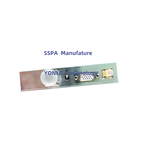
SMA-Female,  50 Ohms

10

Dimension

180*92*25mm (Exclusive Connector)

11

Power Supply Port

Pull-core Capacitor

12

Working Temperature

-25----+65℃

13

Protection

Shutdown more than 75℃, auto-restart less than 50℃

Shutdown when reversed power more 15W, auto-restart after about 30s


I/O Port

DB15F

Description

IN/Out (D/A)

PIN1

1dB (Hang in air or add 5V: No ATT;  Grounding: Enable ATT)

IN, Data

PIN2

2dB (Hang in air or add 5V: No ATT;  Grounding: Enable ATT)

IN, Data

PIN3

4dB (Hang in air or add 5V: No ATT;  Grounding: Enable ATT)

IN, Data

PIN4

8dB (Hang in air or add 5V: No ATT;  Grounding: Enable ATT)

IN, Data

PIN5

16dB (Hang in air or add 5V: No ATT;  Grounding: Enable ATT)

IN, Data

PIN7

Pr (reversed RF Power, 0.05V/dB,  10dB range,  2-2.3V@40dBm)

Out, Analog

PIN10

Pf (Forward RF Power, 0.05V/dB,  20dB range,  2-2.3V@47dBm)

Out, Analog

PIN11

EN (5V: PA OFF; Hang in air or grounding: PA ON)

IN, Data

PIN12

TA (Temperature alarm, Alarm: 5V, Normal: 0V)

Out, Data

PIN13

VA (VSWR Alarm, Alarm: 5V, Normal: 0V)

Out, Data

PIN14

Tc (Temperature:0.01V/1℃,  0.75V @25  )

Out, Analog

PIN15

GND

GND

Get a Free Quote

Our representative will contact you soon.
Email
Name
Company Name
Message
0/1000

Get a Free Quote

Our representative will contact you soon.
Email
Name
Company Name
Message
0/1000
inquiry

Get a Free Quote

Our representative will contact you soon.
Email
Name
Company Name
Message
0/1000
11 16ghz 535w amplifier -0 11 16ghz 535w amplifier -1 11 16ghz 535w amplifier -2 11 16ghz 535w amplifier -3

Related Search