
Frequency:1.8/1.9/2.1/2.6GHz
Pout: >200W
Modulation Type: CW/FM/AM
Working Voltage: 28VDC
|
Place of Origin: |
Shenzhen,China |
|
Brand Name: |
YONLIT, OEM,ODM |
|
Model Number: |
HPG47(410-440MHz) |
|
HPG47(920-928MHz) |
|
|
HPG47(2400-2500MHz) |

Main Applications: Control & Vedio transmission of UAV & Drone
Key specification:
Pout 200W at any frequency in 1.8GHz, 1.9GHz, 2.1GHz, 2.6GHz
Pout20W from -25℃ to 80℃
Description(short)
Competitive Advantage:
* Over-high VSWR to avoid or reduce the damage from any mismatch
* Over-high temperature protection, Shutdown more than 75℃, auto-restart less than 50℃
Remarks
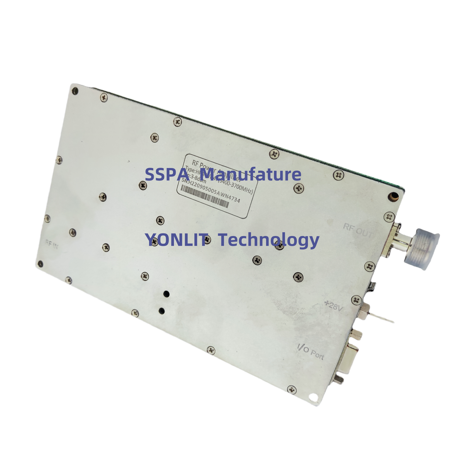
Description
Drones are one of the main forms of conflict in the current market. Countering and jamming drones is the main contradiction. Interference and jamming of drones start from the following aspects:
At present, remote control transmitters have generally adopted frequency hopping and spread spectrum technology, and the frequency hopping parameters can also be adaptive, with a certain anti-interference ability. When calculating the required interference size, the parameters of frequency hopping and spread spectrum must be known to obtain accurate results. However, we can still know the approximate range of the required interference. The remote control transmitter still uses the above parameters. Assuming that the defender is 100 meters away from the drone and the antenna gain is 3dB, if relevant interference is used, the required interference power is close to the remote control transmission power, that is, more than 0.1W. If there are frequency hopping measures in the remote control signal, and the interferer does not know any parameters of these measures except the frequency band range, and can only use noise for full-band violent coverage, then the required power will be increased. As a rule of thumb, it is usually necessary to increase by 30dB, specifically 200W.
Specifications:
No. |
Item |
Description |
||
1 |
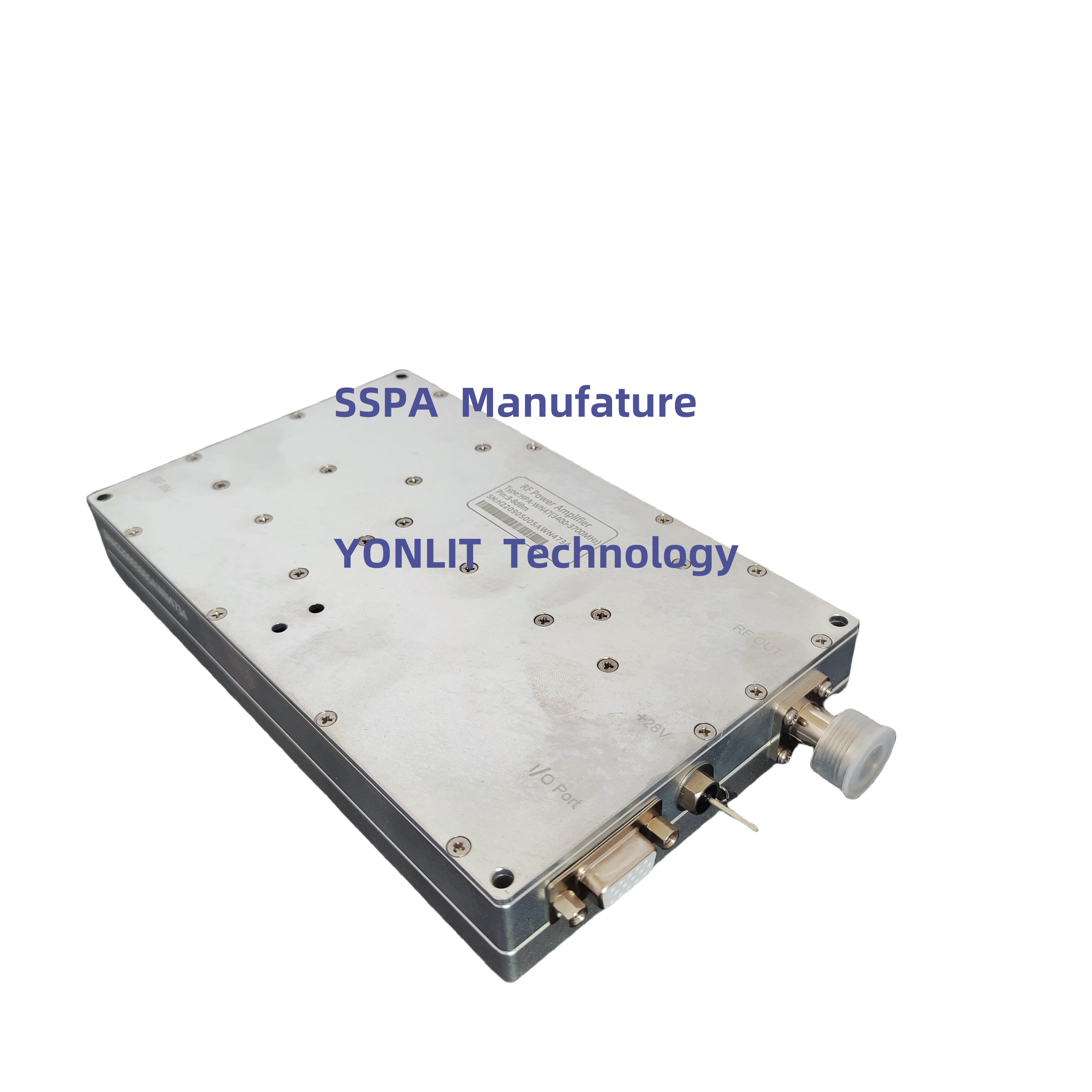
Frequency Range |
1805-1880MHz |
||
1930-1990MHz | ||||
2110-2170MHz | ||||
2620-2690MHz | ||||
or Customized | ||||
2 |
Max Pout |
53dBm±0.5dB (over Frequency at same temperature) |
||
53dBm±0.5dB (over temperature at same Frequency) | ||||
3 |
Pin range |
0dBm |
||
4 |
Max undamaged Pin |
12dBm |
||
5 |
Gain |
53dB±1.5dB (over Frequency at same temperature) |
||
6 |
Gain Adjust |
31dB; 1dB Step; ±1.5dB Err (at Pin<-8dBm) |
||
7 |
RF Port VSWR |
≤1.5, 50 Ohms |
||
8 |
Working Voltage |
<18A @28VDC±1V |
||
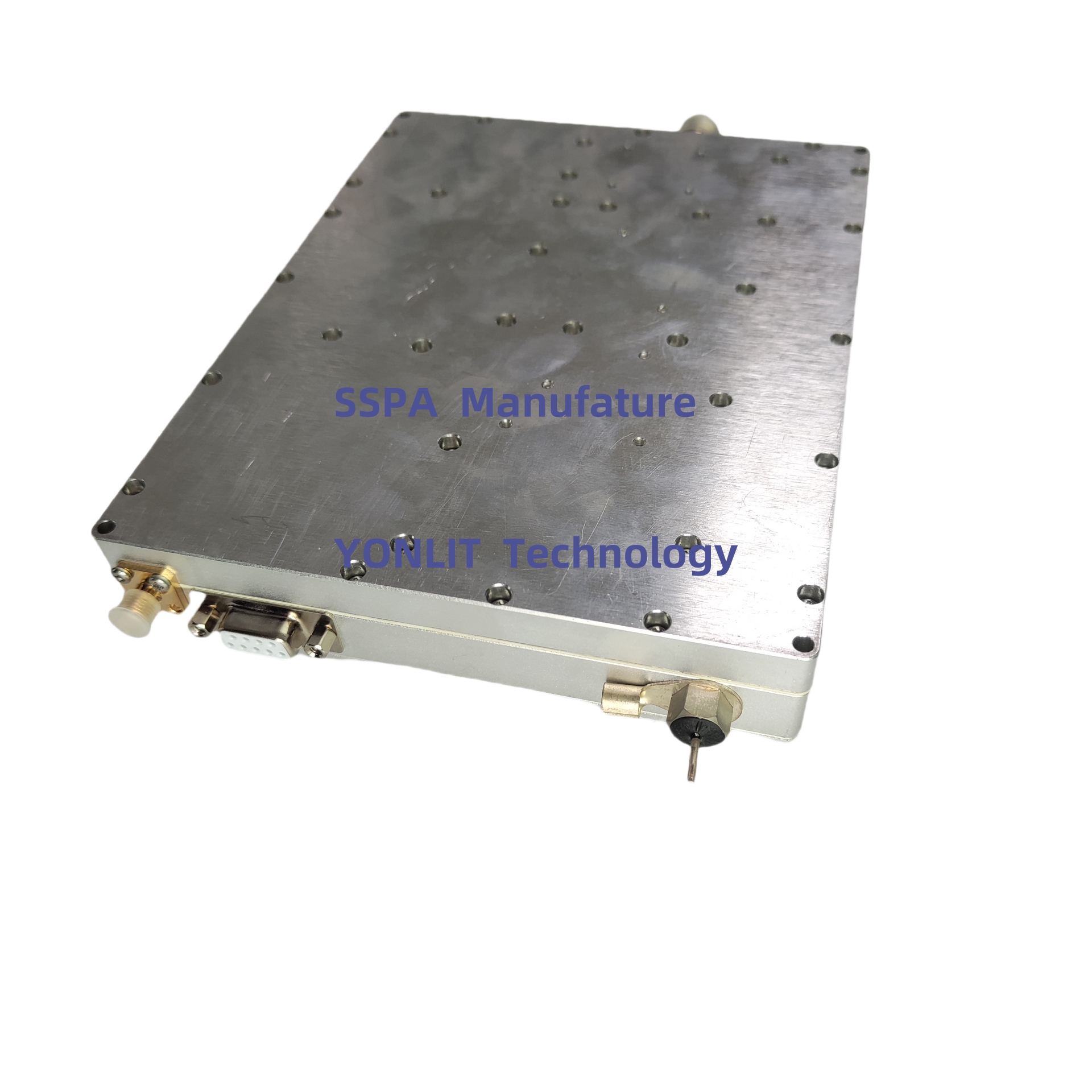
9 |
RF IN Port |
SMA - Female |
||
10 |
RF Out Port |
NK |
||
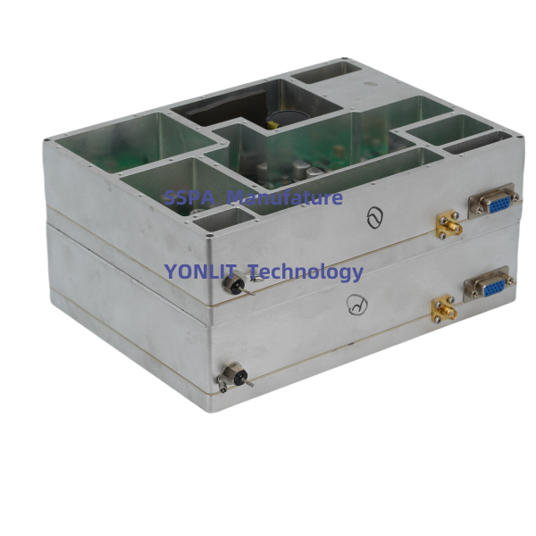
11 |
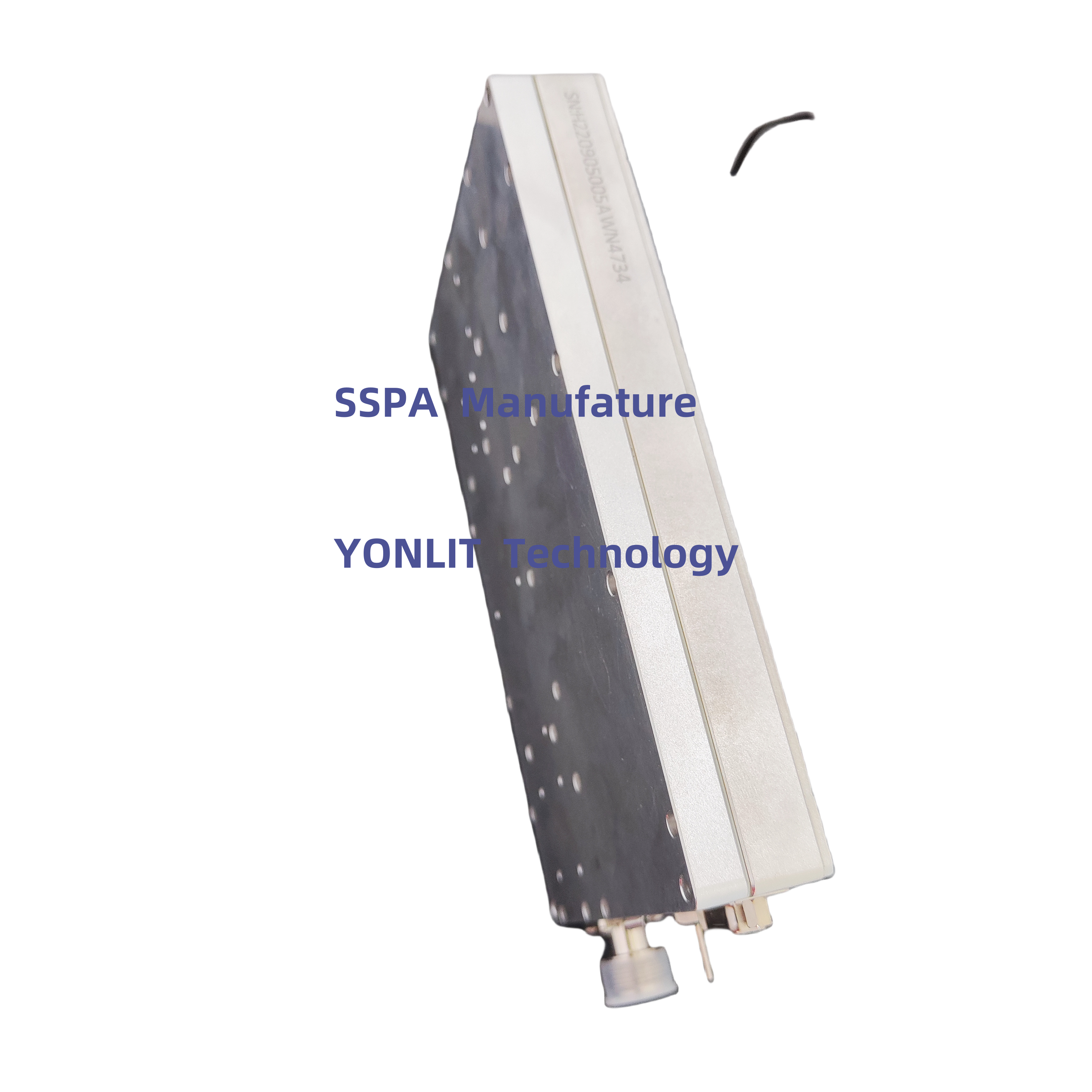
Dimension |
Type A |
180*155*27mm (Exclusive Connector) |
|
Type B |
180*150*27mm (Exclusive Connector) |
|||
12 |
Power Supply Port |
DSUB (2W2-Male or ) |
||
13 |
Working Temperature |
-25----+65℃ |
||
14 |
Protection |
Shutdown more than 75℃, auto-restart less than 50℃ |
||
Shutdown when High-VSWR, auto-restart after about 30s | ||||
15 |
I/O |
Parallel |
TTL, DB15 Female |
|
Serial |
RS485 |
|||
I/O Port
DB15 |
Description |
IN/Out (D/A) |
|
PIN1 |
1dB |
Hang in air or add 5V: No ATT; Grounding: Enable ATT |
IN, data |
PIN2 |
2dB |
Hang in air or add 5V: No ATT; Grounding: Enable ATT |
IN, data |
PIN3 |
3dB |
Hang in air or add 5V: No ATT; Grounding: Enable ATT |
IN, data |
PIN4 |
4dB |
Hang in air or add 5V: No ATT; Grounding: Enable ATT |
IN, data |
PIN5 |
5dB |
Hang in air or add 5V: No ATT; Grounding: Enable ATT |
IN, data |
PIN6 |
Preset |
When protection occurs, input a pulse signal to reset PA |
IN, Data |
PIN7 |
Pr |
Reversed RF Power Indicator (V) |
Out, Analog |
PIN10 |
Pf |
Forward RF Power Indicator (V) |
Out, Analog |
PIN11 |
EN |
0V or hanging: PA on; 5V: PA off |
IN, Data |
PIN12 |
TA |
||


 EN
EN