Frequency: 2700-3100MHz
Pout: >500W
Modulation Type: Pulsed
Working Voltage: 28VDC
|
Place of Origin: |
Shenzhen, China |
|
Brand Name: |
YONLIT, OEM,ODM |
|
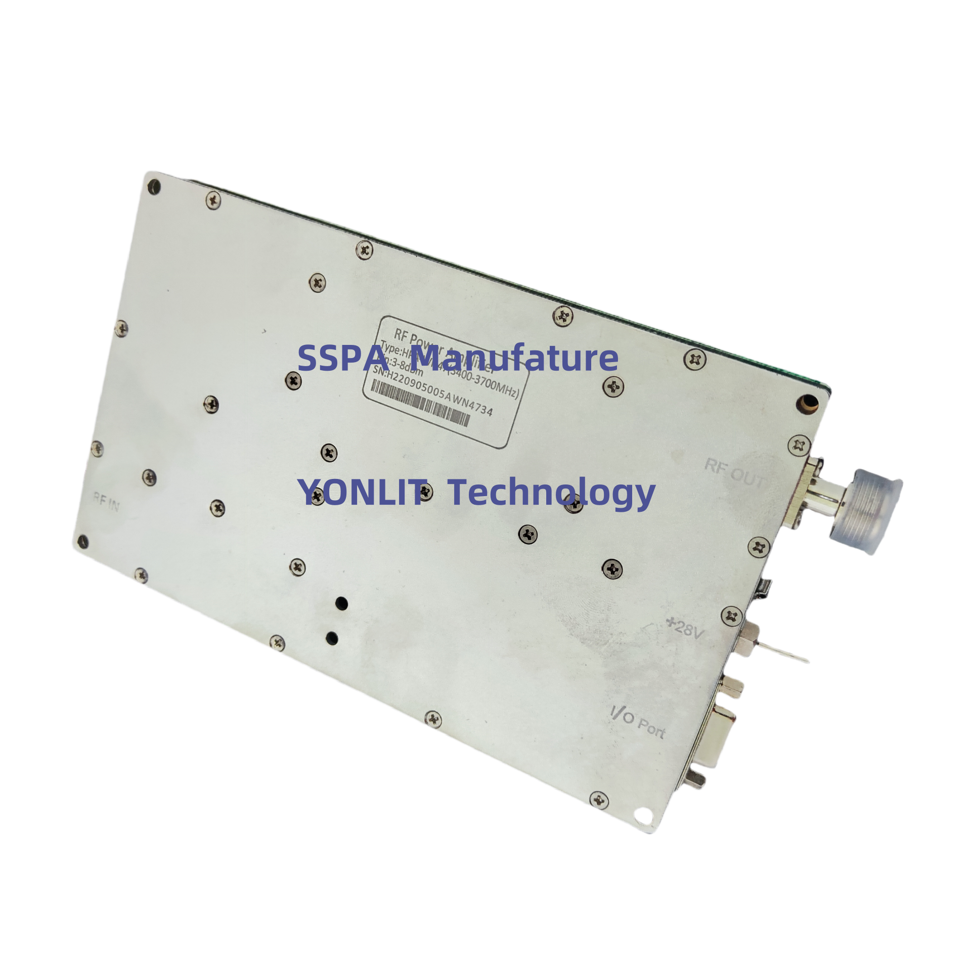
Model Number: |
HPP57(2.7-3.1GHz) |

Feature:
Applications:
For Phased Array RADAR, Electronic warfare, electronic countermeasure, SDR,
Description
• Any malfunction or damage to the amplifier caused by improper operation that violates the following instructions will not be covered by the warranty.
• Please notice that the Pin (peak) is completely different from Pin (average). 200 µs, 20%, 6dBm Pin (peak) is actually -1dBm Pin (average).
• PA should operate on an appropriate radiator, and it's recommended to paste the silicon grease in between. Otherwise, PA would be shut down by high temperatures;
• PA’s output port cannot open or short;
• PA’s output port should connect to a proper load (Load: Either an attenuator connects with a power meter or an antenna. The VSWR of the load should be less than 1.3);
• The Pin range and polarity of the power supply must be correct;
• Verify and ensure the input signal with instruments that comply with the following requirements:
Frequency: 2.7-3.1GHz
Pulse duty: < 20%e
Pulse width: <200µs
Pin: 3-6dBm(peak)
• Pout probably is lower the rated power if the Pin is lower than 3dBm; PA probably is damaged if the Pin is higher than 15dBm;
• Ensure that the power supply voltage meets 48VDC ± 1VDC;
• Ensure that all of the above requirements are met. Turn on the power switch then the amplifier can work properly.
Specifications:
No. |
Item |
Specification |
|
1 |
Frequency |
2.7 -2.9GHz |
|
2.9-3.1GHz | |||
2.7-3.1GHz | |||
3.1-3.4GHz | |||
3.1-3.5GHz | |||
customized | |||
2 |
Pout (Pulse ,Peak) |
2.7 -2.9 GHz |
57dBm±1dB (500W) |
2.9-3.1GHz |
57dBm±1dB (500W) |
||
2.7-3.1GHz |
56dBm±1dB (400W) |
||
3.1-3.4GHz |
56dBm±1dB (400W) |
||
3.1-3.5GHz |
55dBm±1dB (300W) |
||
3 |
Pin |
3-6dBm (Pulse, Peak) |
|
4 |
Max Pin ( undamaged level) |
10dBm (Pulse, Peak) |
|
5 |
Pulse width |
<200 us |
|
6 |
Pulse Duty cycle |
<20% |
|
7 |
Pulse Rise/Fall time |
<100 ns |
|
8 |
RF IN/OUT VSWR |
<2 |
|
9 |
Harmonic suppression |
50dBc |
|
10 |
Spurious emission |
50dBc |
|
11 |
Working temperature |
-25℃ to 65℃ |
|
12 |
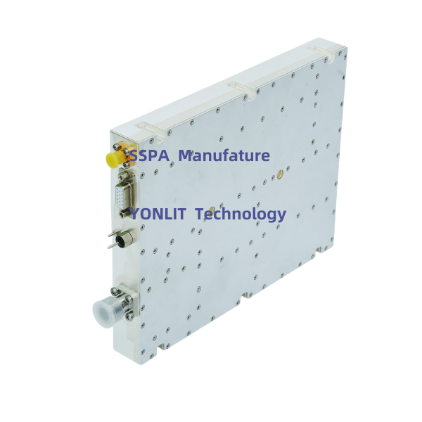
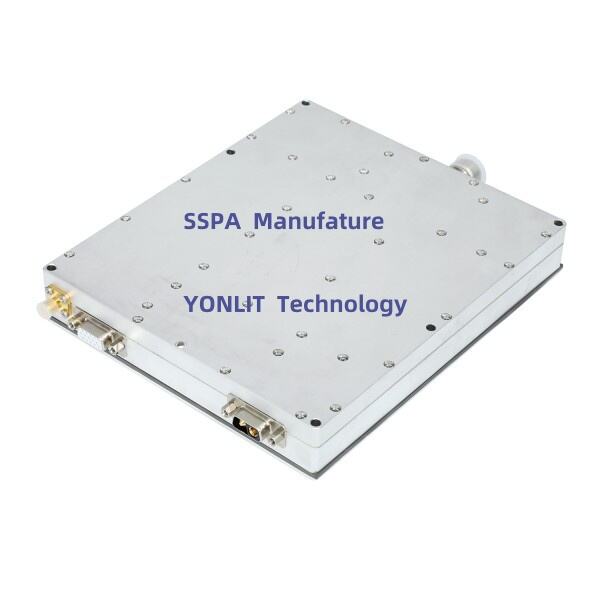
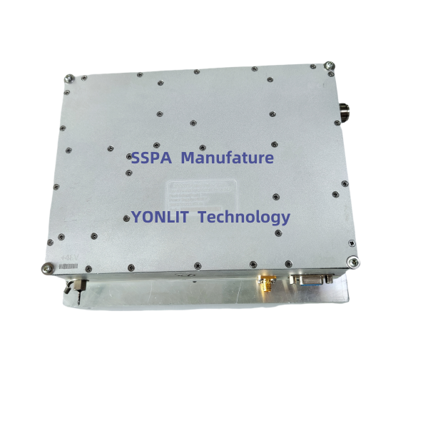
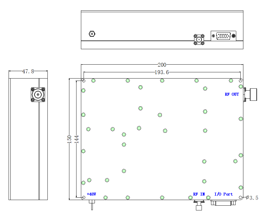
RF IN Connector |
SMA-Female |
|
13 |
RF OUT Connector |
N-Female |
|
14 |
Ic (Quiescent) |
0.5-0.8A |
|
15 |
Ic (Working Average) |
<4-5A |
|
16 |
Supply voltage |
48VDC±1VDC |
|
17 |
Dimension |
220*150*50mm |
|
18 |
Protection |
* Shutdown over High-VSWR and Auto-restart |
|
Shutdown over High-Temperature and Auto-restart | |||
I/O Port (DB15 Female)
|
*PIN6: Pulse Switch (+5V: ON; Hang in air or 0V : OFF) *PIN9: +5V (out) PIN6 and PIN9 is connected (default) |
PIN7: Pr (Reversed RF Power ) |
PIN10:Pf (Forward RF Power ) |
PIN11: Enable PA (5V: PA OFF; Hang in air or grounding: PA ON) |
PIN12:TA (Temperature alarm, Alarm: 5V; Normal: 0V) |
*PIN13: VA (VSWR Alarm, Alarm: 5V; Normal: 0V) |
PIN14:Tc (Temperature: 0.01V/1℃, 0.75V @25 ℃) |
PIN15: GND |
PIN1-PIN5, PIN8: NC. |
Remarks:
1:PA should be fixed on flat Radiator with screws (thermal grease) .
2:Input level of PA should be 2.9-3.1GHz, Pulse duty <20%, Pulse width <200us, 3-6dBm; otherwise PA maybe broken.
3:PA should connected to load before Power on PA ; otherwise PA maybe broken。
4. Instructions
Any malfunction or damage to the amplifier caused by improper operation that violates the following instructions will not be covered by the warranty.
• Please notice that the Pin (peak) is completely different from Pin (average). 200 µs, 20%, 6dBm Pin (peak) is actually -1dBm Pin (average).
• PA should operate on an appropriate radiator, and it's recommended to paste the silicon grease in between. Otherwise, PA would be shut down by high temperatures;
• PA’s output port cannot open or short;
• PA’s output port should connect to a proper load (Load: Either an attenuator connects with a power meter or an antenna. The VSWR of the load should be less than 1.3);
• The Pin range and polarity of the power supply must be correct;
• Verify and ensure the input signal with instruments that comply with the following requirements:
Frequency: 2.9-3.2GHz
Pulse duty: < 20%e
Pulse width: <200µs
Pin: 3-6dBm(peak)
• Pout probably is lower the rated power if the Pin is lower than 3dBm; PA probably is damaged if the Pin is higher than 15dBm;
• Ensure that the power supply voltage meets 48VDC ± 1VDC;
• Ensure that all of the above requirements are met. Turn on the power switch then the amplifier can work properly.


 EN
EN