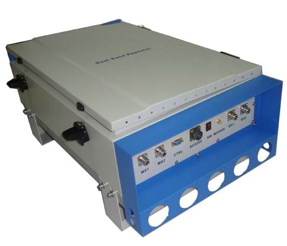

Main feature
Deep understanding of mobile communication system based on our company, through the rational allocation of radio frequency component index and optimize RF system, to ensure the excellent performance of RF link;
The uplink low noise suppression and inhibition of threshold, on the downlink power balance, the downlink, the out-of-band rejection, system dynamic range, transmission delay system important parameter, carries on the thorough analysis, careful design, strict control, so the machine has characteristics of good.
Modular design is the development trend of the design, convenient for users to upgrade, maintenance system. In order to meet the needs of the market, through detailed analysis and system demonstration unit, the reasonable partition decomposition module and the appropriate index, forming a repeater module system flexible and efficient, laid the foundation for a variety of models of the flexible collocation.
Features of Digital fiber optic repeater optical
Classify |
feature |
Emission wavelength |
master:1310 nm ; slave:link 3:1550nm;link 4:1310nm |
The light output power |
-9dBm~-3dBm |
Optical fiber transmission distance |
20km |
Connector type |
master:LC/UPC ;slave: FC/PC |
Specifications for digital fiber repeater(With diversity)
item |
Technical parameters |
||
downlink |
uplink(main) |
uplink(diversity) |
|
Frequency range(select) |
951-869MHz 935-960MHz 1805-1880MHz |
806-824MHz 890-915MHz 1710-1785MHz |
806-824MHz 890-915MHz 1710-1785MHz |
The max of carriers |
12 |
12 |
12 |
The max output power |
10W:40dBm±2 20W:43dBm±2 40W:46dBm±2 60W:48dBm±2 |
0dBm±2 |
0dBm±2 |
Noise figure |
———— |
≤5dB |
≤5dB |
Max gain |
50±2dB |
50±2dB |
50±2dB |
Gain adjustment |
30dB |
30dB |
30dB |
Gain adjustment step |
1dB |
1dB |
1dB |
Automatic level control(ALC) |
At the maximum power, and increase input 10dB, output power variation less than 2dB, when the input signal level increased more than 10dB, the output power should be kept within the maximum output power of ± 2dB. |
||
Band wave |
≤3dB |
||
VSWR |
≤1.5 |
||
Inter-modulation attenuation |
In-Band inter-modulation≥40dBc (2 carrier,40dBm) Out of band≥40dBc(2carrier,40dBm) |
||
Carrier frequency band rejection |
400 KHz £ f_offset < 600 KHz ≥35dB 600 KHz £ f_offset < 1MHz ≥56dB 1MHz £ f_offset < 5 MHz ≥60dB 5 MHz £ f_offset ≥60dB note:f_offset is offset carrier center frequency |
||
Stray emission-carrier stray(peak) |
f0±100kHz≤0.5dBc/30kHz f0±200kHz≤-30dBc/30kHz (-36dBm/3kHz) f0±400kHz≤-60dBc/30kHz (-36dBm/3kHz) f0±600kHz≤-60dBc/30kHz(-27dBm/30kHz) |
||
Stray emission-work with internal stray emission(peak) |
≥60dBc/30kHz或≤-36dBm/100kHz |
||
Stray emission-working out of band(deviation from the band edge 2.5MHz besides) (peak) |
9~100kHz:≤-36dBm/1kHz |
||
100kHz~50MHz:≤-36dBm/10kHz | |||
50~822.5MHz:≤-36dBm/100kHz | |||
822.5~837.5MHz:≤-47dBm/100kHz | |||
837.5~867.5MHz:≤-36dBm/30kHz | |||
867.5~880MHz:≤-47dBm/30kHz | |||
880~915 MHz:≤-98dBm/30kHz(900MHzjust test down link) | |||
915~935MHz:≥60dBc/30kHz or -36dBm/100kHz(ordinary,900MHz just test down link) | |||
956.5~962.5 MHz:≤-36dBm/30kHz(900MHz just test down link) | |||
962.5 MHz~1GHz:≤-36dBm/100kHz(900MHz just test down link) | |||
882.5~887.5 MHz:≤-36dBm /100kHz(900MHz just test up link) | |||
911.5~962.5MHz:≤-36dBm /30kHz(900MHz just test up link) | |||
882.5~1000MHz:≤-36dBm /100kHz(1800MHzjust test down link) | |||
1~1.71GHz:≤-30dBm/1MHz | |||
1~1.7075:≤-30dBm/1MHz(1800MHz just test up link) | |||
1.7275~1.92GHz:≤-47dBm/100kHz(1800MHz just test up link) | |||
1.71GHz~1.8025 GHz≤-47dBm/100kHz(1800MHz just test down link) | |||
1.8225~1.92GHz:≤-47dBm/100kHz(1800MHz just test down link) | |||
1.71~1.92GHz:≤-47dBm/100kHz(only 900MHz) | |||
1.920~1.980GHz:≤-62 dBm/100kHz | |||
1.980~2.010GHz:≤-36dBm/100kHz | |||
2.010~2.025GHz:≤-62 dBm/100kHz | |||
2.025-2.100GHz:≤-36dBm/100kHz | |||
2.100~2.170GHz:≤-62 dBm/100kHz | |||
2.170~3.4GHz:≤-30dBm/1MHz | |||
3.4~3.53GHz:≤-47dBm/100kH | |||
3.53~12.75GHz:≤-30dBm/1MHz | |||
|
In-band carrier leak(Harmonic superposition)
|
In the digital modulation mode due to the DC drift data and folding upper and lower frequency caused by the band carrier leakage caused to the other carrier with the same frequency interference effects.In-band carrier leak≥60dB or ≤-36dBm |
||
|
Blocking gain reduction is not more than 6dBm
|
F1-20 MHz~F1-2.5 MHz( -40 dBm/signal) F2+2.5 MHz~F2+20 MHz (-40 dBm/signal) 851 MHz~880 MHz( -30 dBm/cw signal) 921 MHz~960 MHz( -30 dBm/cw signal) 1805 MHz~1880 MHz( -30 dBm/cw signal) 1880~1920 MHz( 10 dBm/cw signal) 2010 MHz ~2025 MHz( -30 dBm/cw signal) 2110~2170 MHz( -30 dBm/cw signal) 2300 MHz ~2400 MHz( -30 dBm/cw signal) 2400~2483.5 MHz( -30 dBm/cw signal) 806 MHz~835 MHz( -15 dBm/cw signal) 885 MHz~915 MHz( -15 dBm/cw signal)(not contrapose 900MHz frequency equipment) 1710 MHz~1785 MHz( -15 dBm/cw signal) 1920~1980 MHz( -15 dBm/cw signal) |
||
Transmission delay |
System delay:≤25μs(use one trailer 6,optical use short tail fiber 1m); |
||
Delay compensation range:≥ 100μs With automatic and manual compensation, after compensation of the remote TA; | |||
Delay correction step:≤1μs; | |||
Modulation accuracy |
Test condition::Set up and down the gain of 45dB, input range of -10 to +5dBm downlink, uplink input range of -90 ~ -40dBm, shall meet the following requirement Frequency error:-45Hz≤ΔF≤+45Hz EVM(RMS):≤6% ; |
||
Max video input(not damage) |
uplink:10dBm (slave input port) downlink:10dBm (master input port) |
||
Uplink noise suppression ability |
Uplink gain=45dB situation,Noise suppression and control equipment for uplink output noise floor≤-87dBm |
||
With different carrier of different time slots respectively control function | |||
Noise free level transition adjustment,adjustment range≥30dB,the adjustment range of low-end shall not be higher than -108dBm | |||
Adjustment stype≤2dB | |||
The noise setting method:each remote should be able to set the threshold of the noise | |||
Optical bypass function |
Work among remote equipment failure or optical processing equipment cascade behind the fault occurs is not affected |
||
Optic loop function |
When the remote equipment power or optical interrupt occurs, followed by loop cascade equipment can work normally. |
||
The total length of time slot occupation statistical error rate |
≤10%,Requires statistical uplink time slot occupied total length, respectively according to the different remote statistics. |
||
Monitoring interface:local,RS232 or ethernet port;long-distance, MODEM; | |||



 EN
EN