Frequency:0.7/0.8/0.9GHz
Pout: >100W
Modulation Type: CW/FM/AM
Working Voltage: 28VDC
|
Place of Origin: |
Shenzhen, China |
|
Brand Name: |
YONLIT, OEM,ODM |
|
Model Number: |
HPG50(704-744MHz) |
|
|
HPG50(851-894MHz) |
|
|
HPG50(925-960MHz) |

Main Applications:Control & Vedio transmission of UAV & Drone
Key specification:
Pout 100W at any frequency in 700MHz,800MHz, 900MHz
Pout100W from -25℃ to 80℃
Description
Competitive Advantage:
* Over-high VSWR to avoid or reduce the damage from any mismatch
* Over-high temperature protection, Shutdown more than 75℃, auto-restart less than 50℃
Remarks
Description
Specifications:
No. |
Item |
Description |
1 |
Frequency Range |
704-744MHz |
851-894MHz | ||
925-960MHz | ||
or Customized | ||
2 |
Max Pout |
50dBm±0.5dB (over Frequency at same temperature) |
50dBm±0.5dB (over temperature at same Frequency) | ||
3 |
Pout Adjust
|
If atcual-Pout is not equal to the target-Pout in every 60 micro-seconds, the ATT value need to be increased or decreased by 1dB step in the range of 0-31dB, till the actual-Pout is equal to the target-Pout |
4 |
Pin range |
5-10dBm |
5 |
Gain |
48dB±1.5dB (over Frequency at same temperature) |
6 |
Gain Adjust |
31dB; 1dB Step; ±1.5dB Err (at Pin<-8dBm) |
7 |
RF Port VSWR |
≤1.5, 50 Ohms |
8 |
Working Voltage |
<10A @28VDC±1V |
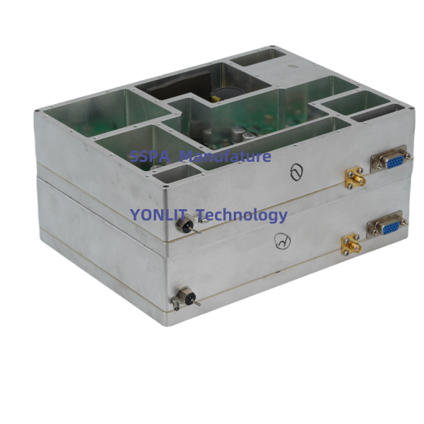
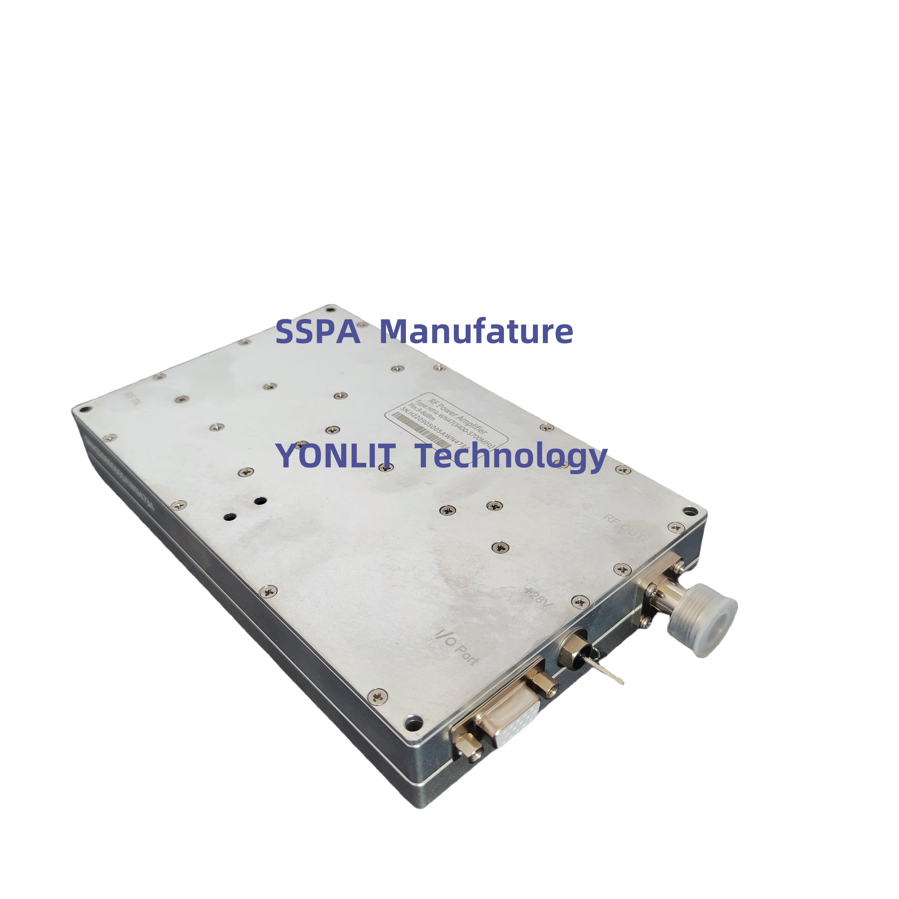
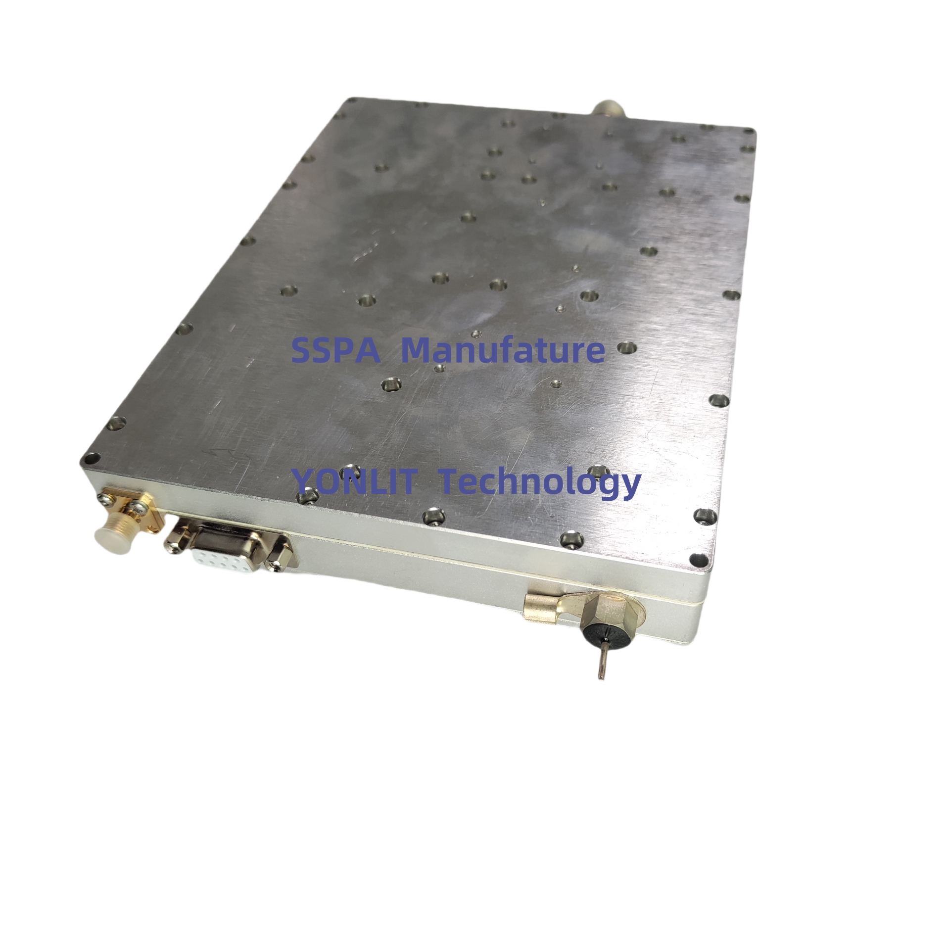
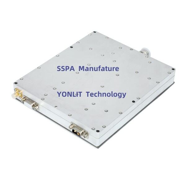
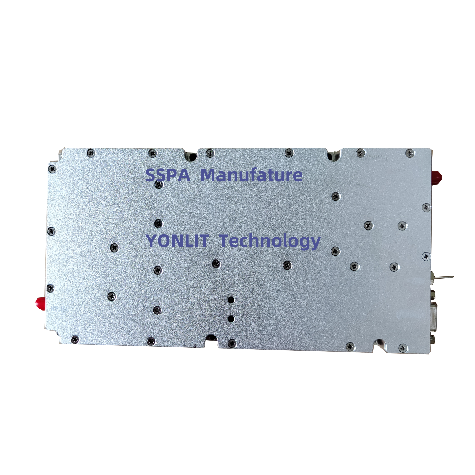
9 |
RF IN Connector |
SMA - Female |
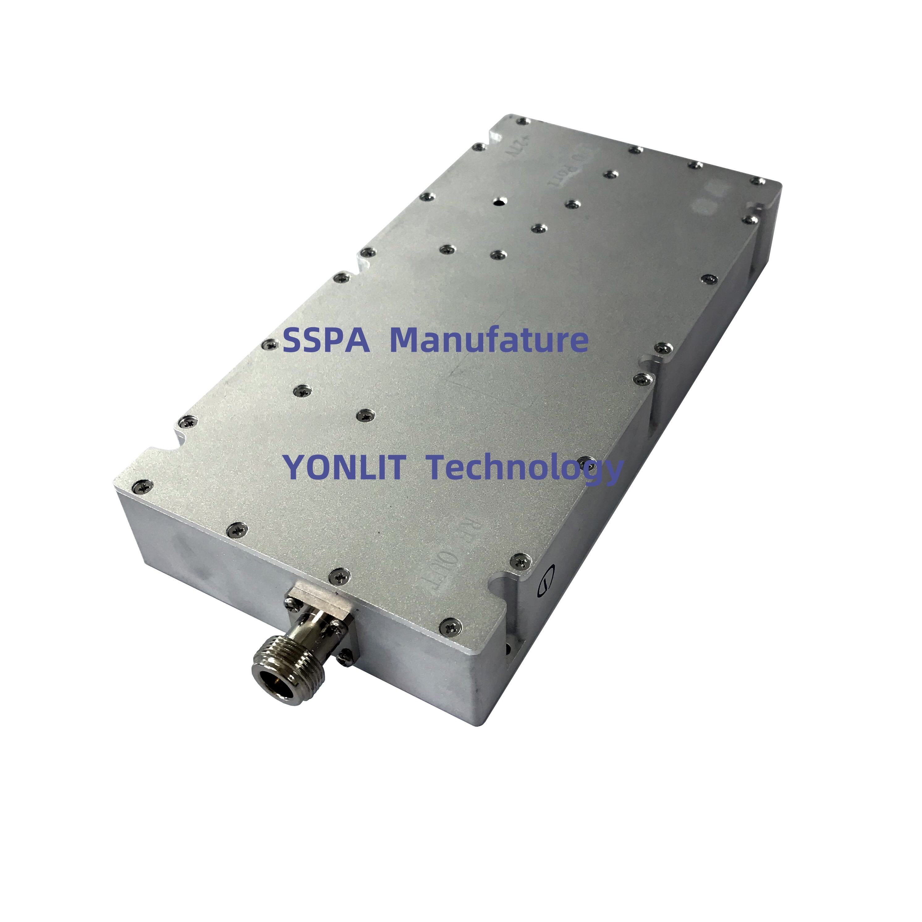
10 |
RF Out Connector |
NK or SMA - Female |
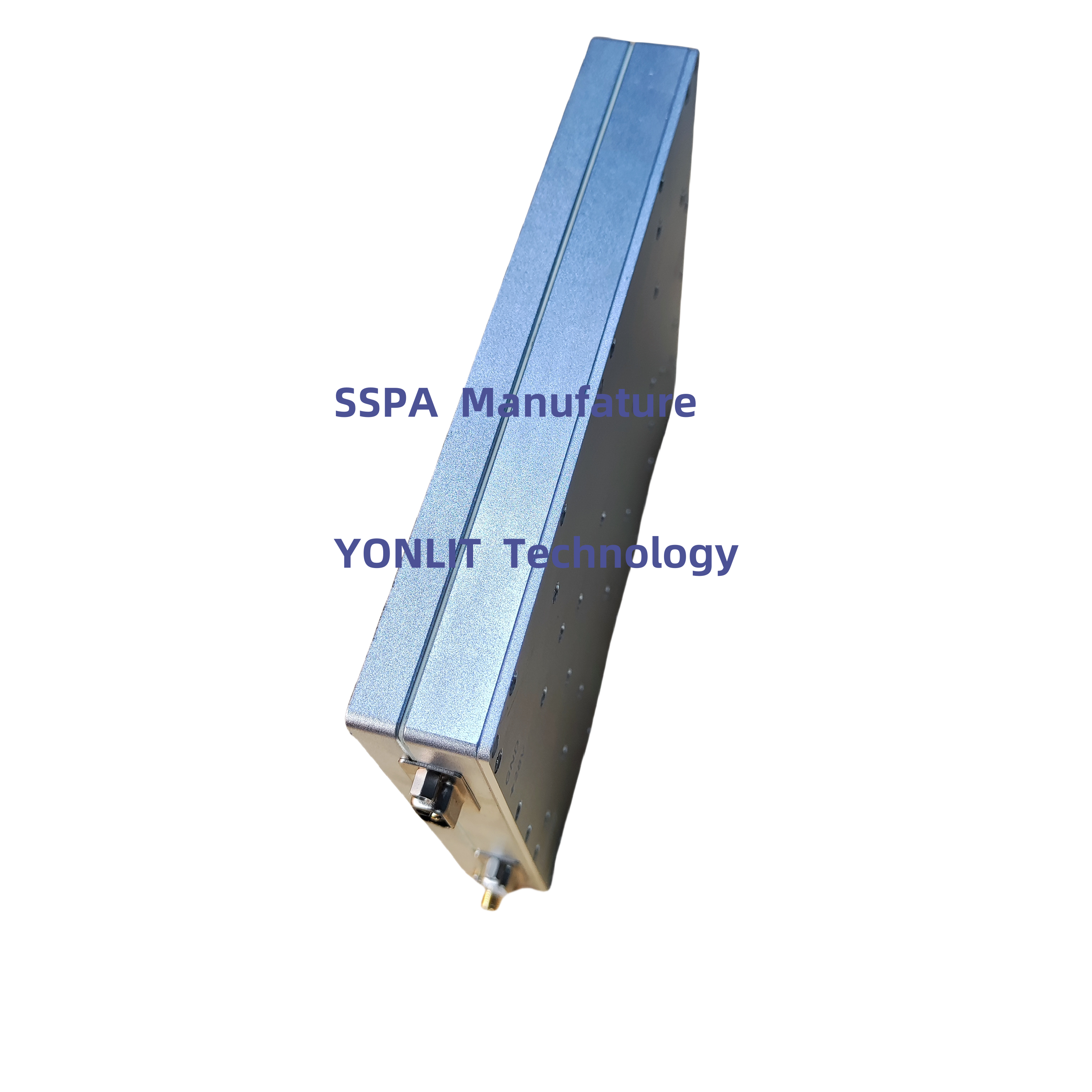
11 |
Dimension |
210*110*25mm (Exclusive Connector) |
12 |
Power Supply Port |
Pull-core Capacitor |
13 |
Working Temperature |
-25----+65℃ |
14 |
Protection |
Shutdown more than 75℃, auto-restart less than 50℃ |
Shutdown when reversed power more 25W, auto-restart after about 30s |
I/O Port
DB15F |
Description |
IN/Out (D/A) |
PIN1 |
1dB (Hang in air or add 5V: No ATT; Grounding: Enable ATT) |
IN, Data |
PIN2 |
2dB (Hang in air or add 5V: No ATT; Grounding: Enable ATT) |
IN, Data |
PIN3 |
4dB (Hang in air or add 5V: No ATT; Grounding: Enable ATT) |
IN, Data |
PIN4 |
8dB (Hang in air or add 5V: No ATT; Grounding: Enable ATT) |
IN, Data |
PIN5 |
16dB (Hang in air or add 5V: No ATT; Grounding: Enable ATT) |
IN, Data |
PIN7 |
Pr (reversed RF Power, 0.05V/dB, 10dB range, 2-2.3V@40dBm) |
Out, Analog |
PIN10 |
Pf (Forward RF Power, 0.05V/dB, 20dB range, 2-2.3V@47dBm) |
Out, Analog |
PIN11 |
EN (5V: PA OFF; Hang in air or grounding: PA ON) |
IN, Data |
PIN12 |
TA (Temperature alarm, Alarm: 5V, Normal: 0V) |
Out, Data |
PIN13 |
VA (VSWR Alarm, Alarm: 5V, Normal: 0V) |
Out, Data |
PIN14 |
Tc (Temperature:0.01V/1℃, 0.75V @25 ℃ ) |
Out, Analog |
PIN15 |
GND |
GND |
I/OOption3: CustomizedRS485, DB9Male
PIN1,PIN2 |


 EN
EN