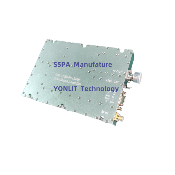
Frequency Range: 400-2700MHz
Pout: >50W
Modulation Type: CW/FM/AM
Working Voltage: 28VDC±1V
Frequency Range: 500-2500MHz
Pout: >100W
Modulation Type: CW/FM/AM
Working Voltage: 28VDC±1V
Frequency Range: 700-2700MHz
Pout: >100W
Modulation Type: CW/FM/AM
Working Voltage: 28VDC±1V
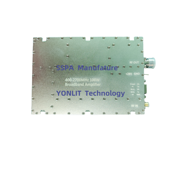
Frequency Range: 400-2700MHz
Pout: >100W
Modulation Type: CW/FM/AM
Working Voltage: 28VDC±1V
Frequency Range: 500-2500MHz
Pout: >150W
Modulation Type: CW/FM/AM
Working Voltage: 28VDC
Frequency Range: 700-2700MHz
Pout: >150W
Modulation Type: CW/FM/AM
Working Voltage: 28VDC
Frequency Range: 20-512MHz
Max Pout: >100W
Modulation Type: CW/FM/AM
Working Voltage: 28VDC±1V
Frequency Range: 100-600MHz
Max Pout: >100W
Modulation Type: CW/FM/AM
Working Voltage: 28VDC±1V
Frequency Range: 2000-6000MHz
Pout: >50W
Modulation Type: CW/FM/AM
Working Voltage: 28VDC±1V
Frequency: 3.4-3.6/3/6-3.8GHz
Pout: >120W
Modulation Type: CW/FM/AM
Working Voltage: 28VDC
Frequency:3.4-3.5/3.5-3.7GHz
Pout: >50W
Modulation Type: CW/FM/AM
Working Voltage: 28VDC
Frequency:1.8/1.9/2.1/2.6GHz
Pout: >200W
Modulation Type: CW/FM/AM
Working Voltage: 28VDC


 EN
EN


