Frequency: 1170-1280MHz
Pout: >200W
Modulation Type: CW/FM/AM
Working Voltage: 28VDC

Main uses: Amplify satellite navigation signals: GPS L1,L2, L4,L5; BDS; GALILEO L1 L5; GLONASS L1,L5.
Key specification:
Pout >200W at any frequency
Pout>200W from -25℃ to 80℃
Description(Short)
Competitive Advantage:
* Over-high VSWR to avoid or reduce the damage from any mismatch
* Over-high temperature protection, Shutdown more than 75℃, auto-restart less than 50℃
Remarks
Description
The GPS signal is very weak and below the natural background noise near the ground. Using commonly used passive antennas with 3-6dB gain in open areas, the total reception level can reach up to about -120dBm. The civilian GPS signal is a spread spectrum signal with a frequency of 1575MHz and a bandwidth of 2.046MHz. The spread spectrum gain is 43dB, and Cb/N0 is considered to be 6dB. Although any form of interference can be effective as long as it is high power, the effectiveness of interference in some frequency bands is poor due to the high spread spectrum gain. Among the easy to implement methods, full band noise interference has an advantage, with a bit error rate higher than 10% when the following conditions are met:
(1)The bandwidth of the interference signal is equal to or greater than 2.046MHz, covering the entire frequency band of the GPS signal. (2) After the interference signal is received by the GPS antenna, its total power level should be higher than -83dBm.
The main lobe direction of the GPS antenna on the drone is facing towards the sky, which can provide some isolation from ground interference. The size of isolation depends on the quality of the antenna, installation method, and the structure and materials of the drone itself. If the antenna is installed in the center position of the drone and there is a whole piece of carbon fiber mesh board on the drone to block the ground direction, it can usually provide 30-40 dB of isolation. If the antenna directionality is poor and the installation is not vertical enough, the isolation will be reduced. Assuming the gain of the drone GPS antenna to the ground defender (interference source) is -40dB, and the gain to the sky meets the requirements for normal GPS antenna reception, that is, the total reception level can reach -120dBm. The drone is 100 meters away from the ground, and the antenna gain of the interference transmitter is 0. According to the free space loss formula, the required transmission power is: Pt= Pr+32.45+ 20logd+ 20logf-G= -83+32.45- 20+ 64+ 40= 33.45dBm.
The above calculation means that if the interference bandwidth is moderate, only 2W of transmission power is needed to kill unmanned aerial vehicle GPS within a range of 100 meters. If the interfering antenna has a 6dB gain, then only 0.5W power is needed. It was found through actual testing that the 0.01W power noise amplitude modulation (1) brand unmanned aerial vehicles extensively use lightweight plastic, resulting in GPS antenna ground isolation being far less than 40dB.
The total received level cannot reach -120dBm (which is close to the theoretical optimal value and is usually considered as -130dBm in engineering).
Specifications:
|
No. |
Item |
Description |
||
|
1 |
Frequency Range |
1170-1280MHz |
||
|
1550-1620MHz |
||||
|
or Customized |
||||
|
2 |
Max Pout |
53dBm±0.5dB (over Frequency at same temperature) |
||
|
53dBm±0.5dB (over temperature at same Frequency) |
||||
|
3 |
Pin range |
0dBm |
||
|
4 |
Max undamaged Pin |
12dBm |
||
|
5 |
Gain |
53dB±1.5dB (over Frequency at same temperature) |
||
|
6 |
Gain Adjust |
31dB; 1dB Step; ±1.5dB Err (at Pin<-8dBm) |
||
|
7 |
RF Port VSWR |
≤1.5, 50 Ohms |
||
|
8 |
Working Voltage |
<18A @28VDC±1V |
||
|
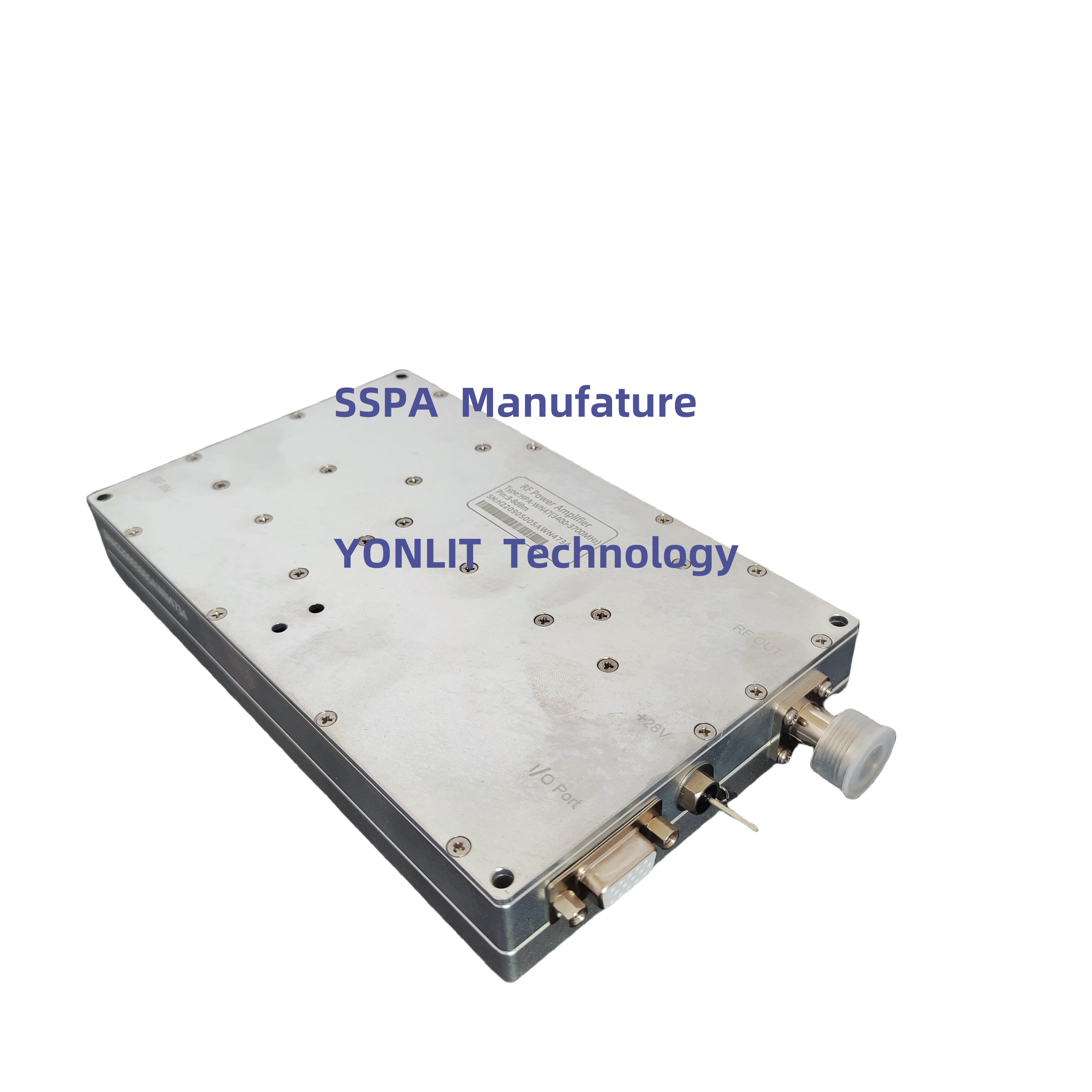
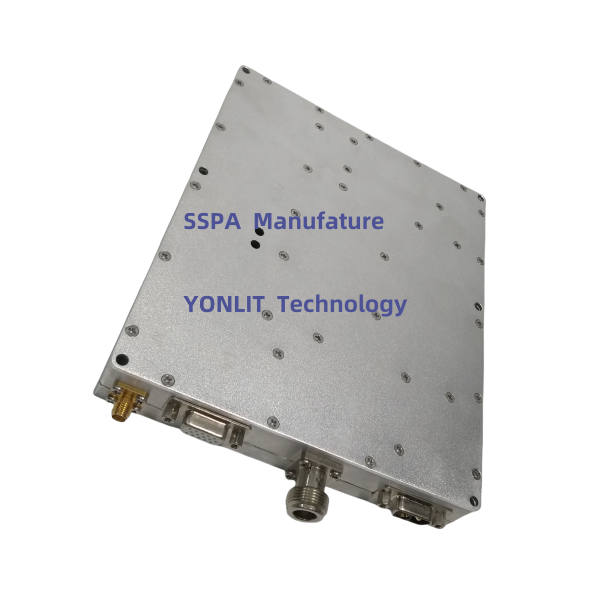
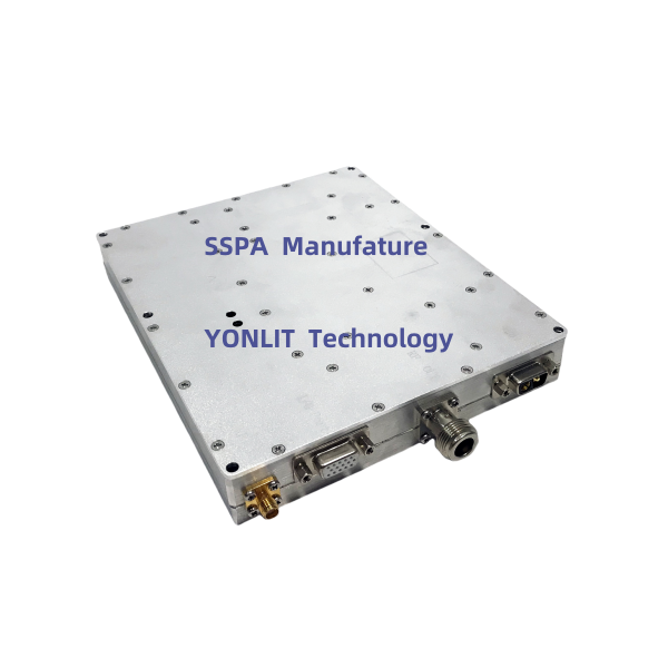
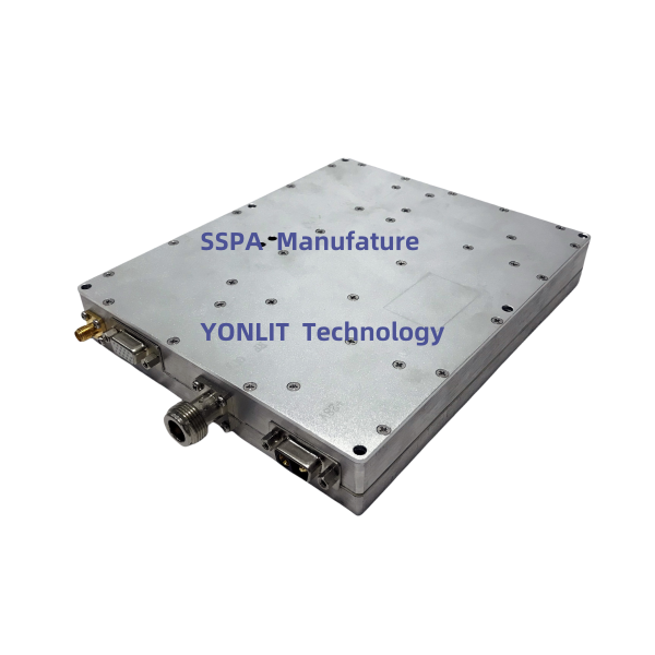
9 |
RF IN Port |
SMA - Female |
||
|
10 |
RF Out Port |
NK |
||
|
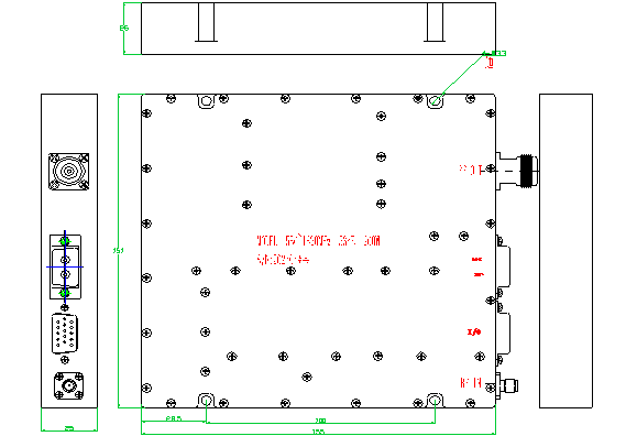
11 |
Dimension |
Type A |
180*155*27mm (Exclusive Connector) |
|
|
Type B |
180*150*27mm (Exclusive Connector) |
|||
|
12 |
Power Supply Port |
DSUB (2W2-Male or ) |
||
|
13 |
Working Temperature |
-25----+65℃ |
||
|
14 |
Protection |
Shutdown more than 75℃, auto-restart less than 50℃ |
||
|
Shutdown when High-VSWR, auto-restart after about 30s |
||||
|
15 |
I/O |
Parallel |
TTL, DB15 Female |
|
|
Serial |
RS485 |
|||
I/O Port
|
DB15 |
Description |
IN/Out (D/A) |
|
|
PIN1 |
1dB |
Hang in air or add 5V: No ATT; Grounding: Enable ATT |
IN, data |
|
PIN2 |
2dB |
Hang in air or add 5V: No ATT; Grounding: Enable ATT |
IN, data |
|
PIN3 |
3dB |
Hang in air or add 5V: No ATT; Grounding: Enable ATT |
IN, data |
|
PIN4 |
4dB |
Hang in air or add 5V: No ATT; Grounding: Enable ATT |
IN, data |
|
PIN5 |
5dB |
Hang in air or add 5V: No ATT; Grounding: Enable ATT |
IN, data |
|
PIN6 |
Preset |
When protection occurs, input a pulse signal to reset PA |
IN, Data |
|
PIN7 |
Pr |
Reversed RF Power Indicator (V) |
Out, Analog |
|
PIN10 |
Pf |
Forward RF Power Indicator (V) |
Out, Analog |
|
PIN11 |
EN |
0V or hanging: PA on; 5V: PA off |
IN, Data |
|
PIN12 |
TA |
Alarm(5V) over High-Teperature and PA shutdown |
Out, Data |
|
PIN13 |
VA |
Alarm(5V) over High-VSWR and PA shutdown |
Out, Data |
|
PIN14 |
Tc |
0.5V +Tc *( 0.01V/℃) |
Out, Analog |
|
PIN15 |
GND |
GND |
/ |
|
PIN8,9 |
Nc. |
/ |
|


 EN
EN