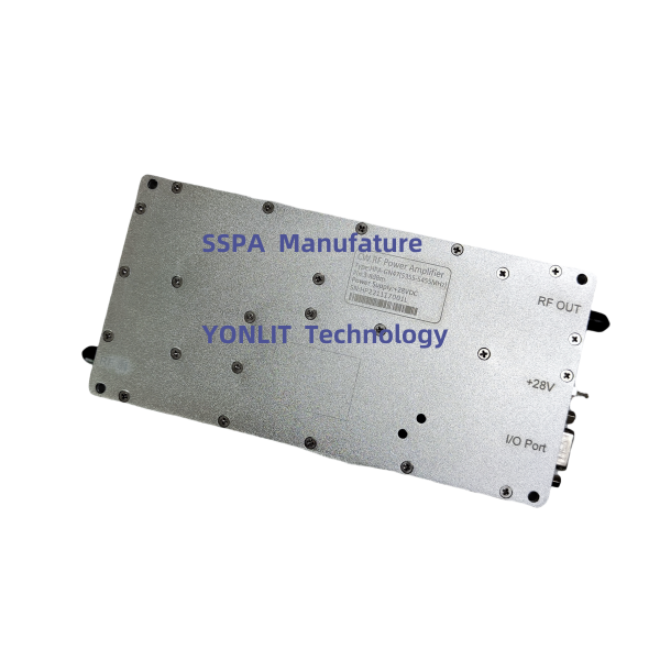
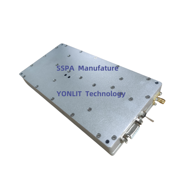
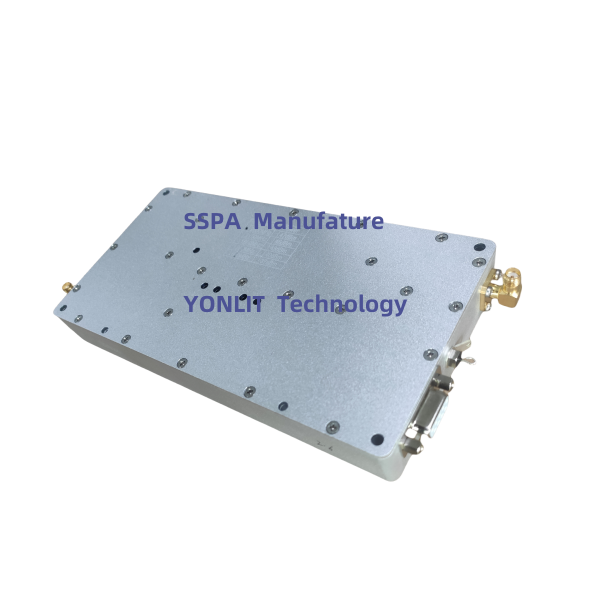
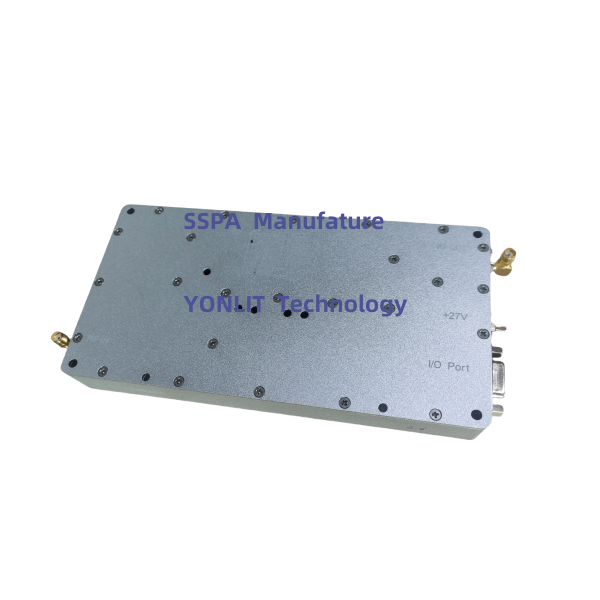
Frequency: 1170-1620MHz
Pout: >100W
Modulation Type: CW/FM/AM
Working Voltage: 28VDC

Main uses: Amplify satellite navigation signals: GPS L1,L2, L4,L5; BDS; GALILEO L1 L5; GLONASS L1,L5.
Key specification:
Pout >100W at any frequency
Pout>100W from -25℃ to 80℃
Description(Short)
Competitive Advantage:
* Over-high VSWR to avoid or reduce the damage from any mismatch
* Over-high temperature protection, Shutdown more than 75℃, auto-restart less than 50℃
Remarks
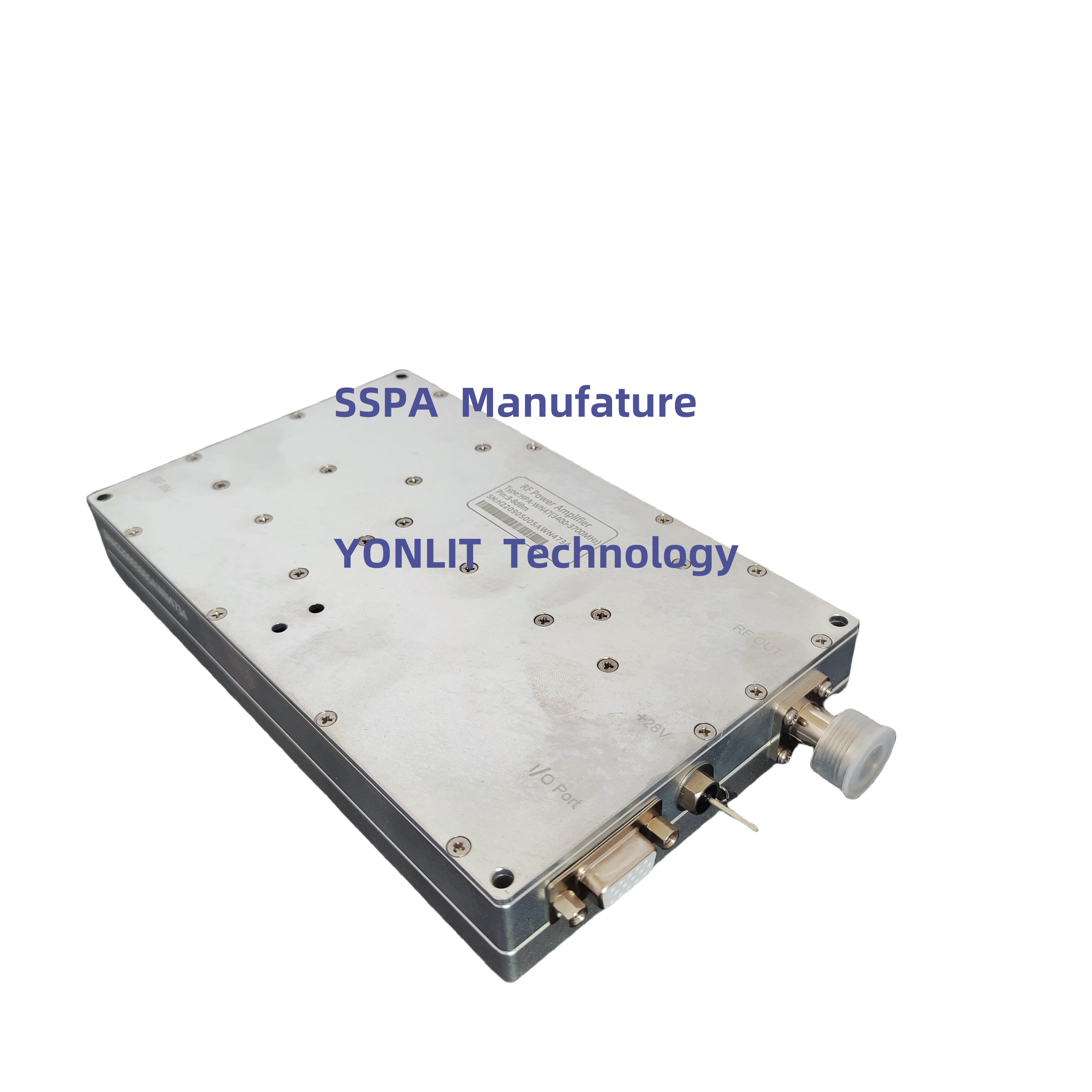
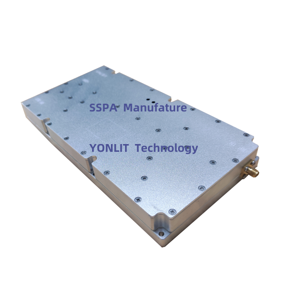
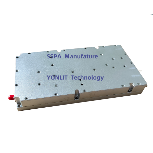
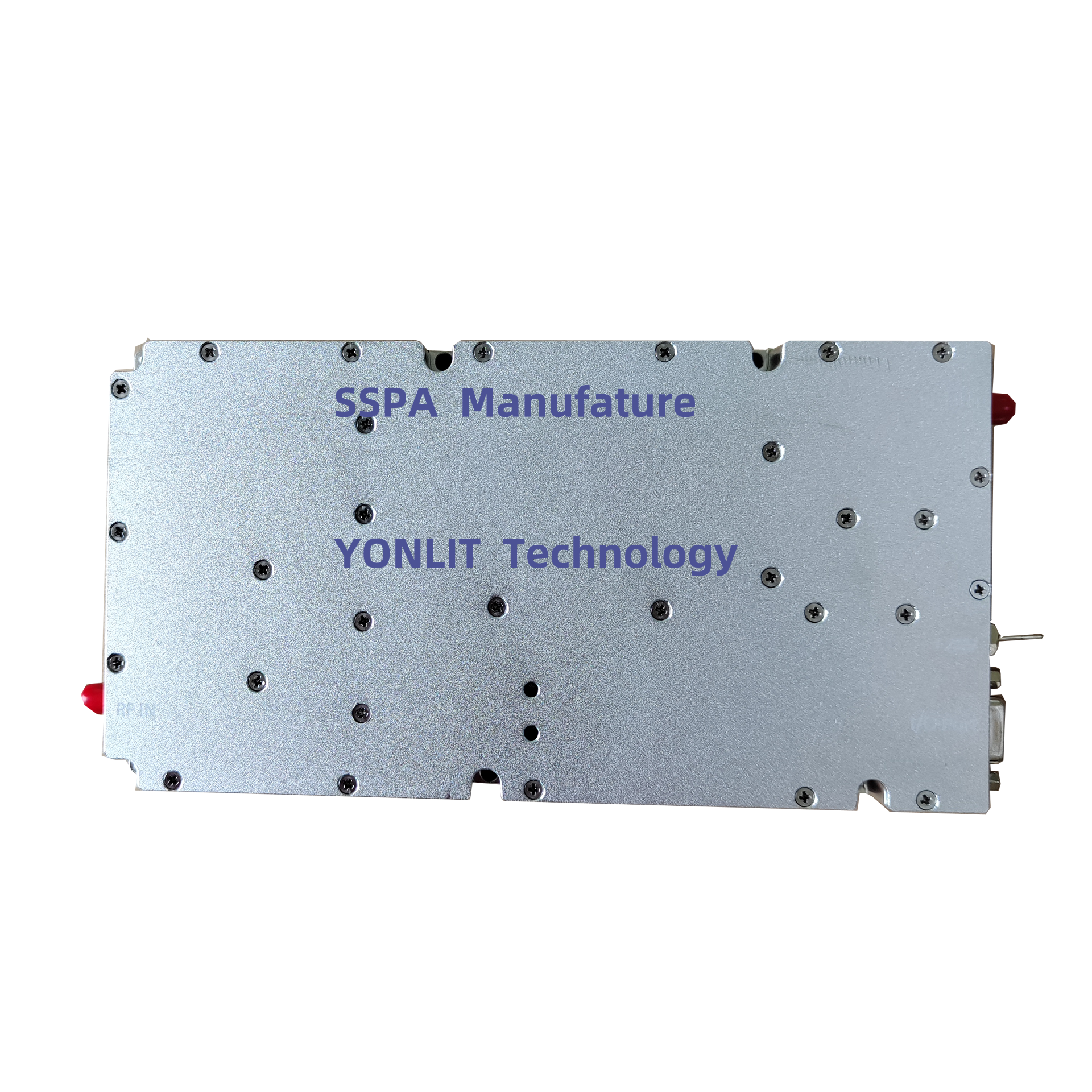
Description
The cheap receiver despreading scheme is too simplified and does not fully utilize the 43dB spreading gain.
The simplest broadband signal is noise frequency modulation. Of course, stronger correlation interference can also be used to deceive, such as using GPS simulators to generate some false signals. But considering that the interference power is already not large, it seems unnecessary to incur this expense.
The behavior of a drone after losing GPS signals depends on the functionality and settings of the flight control system. For skilled operators, GPS is not necessary. In the era without GPS, pilots of aerial models could still complete their envisioned flight routes through visual inspection or image transmission. However, for inexperienced operators, the consequences of eliminating GPS signals are already quite serious, as the automatic return function of the drone has become ineffective and must rely entirely on manual operation. Based on the defense experience already mastered, this is basically equivalent to not being able to fly back. If you want to avoid the consequences of GPS interference, you can write about the following points:
Combined with the antenna with a gain of 5dB, it can already defeat most brands of drones' GPS within a range of 100 meters. This may be caused by the following reasons:
Specifications:
|
No. |
Item |
Description |
|
1 |
Frequency Range |
1170-1620MHz |
|
or Customized |
||
|
2 |
Max Pout |
50dBm±0.5dB (over Frequency at same temperature) |
|
50dBm±0.5dB (over temperature at same Frequency) |
||
|
3 |
Pout Adjust
|
If atcual-Pout is not equal to the target-Pout in every 60 micro-seconds, the ATT value need to be increased or decreased by 1dB step in the range of 0-31dB, till the actual-Pout is equal to the target-Pout |
|
4 |
Pin range |
5-10dBm |
|
5 |
Gain |
>48dB±1.5dB (over Frequency at same temperature) |
|
6 |
Gain Adjust |
31dB; 1dB Step; ±1.5dB Err (at Pin<-8dBm) |
|
7 |
RF Port VSWR |
≤1.5, 50 Ohms |
|
8 |
Working Voltage |
<10A @28VDC±1V |
|
9 |
RF IN Connector |
SMA - Female |
|
10 |
RF Out Connector |
NK or SMA - Female |
|
11 |
Dimension |
210*110*25mm (Exclusive Connector) |
|
12 |
Power Supply Port |
Pull-core Capacitor |
|
13 |
Working Temperature |
-25----+65℃ |
|
14 |
Protection |
Shutdown more than 75℃, auto-restart less than 50℃ |
|
Shutdown when reversed power more 25W, auto-restart after about 30s |
I/O Port
|
DB15F |
Description |
IN/Out (D/A) |
|
PIN1 |
1dB (Hang in air or add 5V: No ATT; Grounding: Enable ATT) |
IN, Data |
|
PIN2 |
2dB (Hang in air or add 5V: No ATT; Grounding: Enable ATT) |
IN, Data |
|
PIN3 |
4dB (Hang in air or add 5V: No ATT; Grounding: Enable ATT) |
IN, Data |
|
PIN4 |
8dB (Hang in air or add 5V: No ATT; Grounding: Enable ATT) |
IN, Data |
|
PIN5 |
16dB (Hang in air or add 5V: No ATT; Grounding: Enable ATT) |
IN, Data |
|
PIN7 |
Pr (reversed RF Power, 0.05V/dB, 10dB range, 2-2.3V@40dBm) |
Out, Analog |
|
PIN10 |
Pf (Forward RF Power, 0.05V/dB, 20dB range, 2-2.3V@47dBm) |
Out, Analog |
|
PIN11 |
EN (5V: PA OFF; Hang in air or grounding: PA ON) |
IN, Data |
|
PIN12 |
TA (Temperature alarm, Alarm: 5V, Normal: 0V) |
Out, Data |
|
PIN13 |
VA (VSWR Alarm, Alarm: 5V, Normal: 0V) |
Out, Data |
|
PIN14 |
Tc (Temperature:0.01V/1℃, 0.75V @25 ℃ ) |
Out, Analog |
|
PIN15 |
GND |
GND |
I/O Option3: Customized RS485, DB9Male
|
PIN1,PIN2 |
RS485A |
|
PIN3,PIN4: |
RS485B |
|
Data Protocol |
China Mobile Standard, Baud Speed: 19200 |


 EN
EN