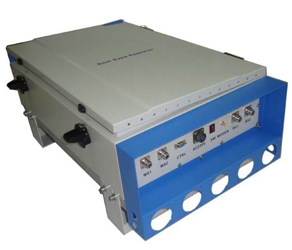

Praecipua Nota
Deep understanding of mobile communication system based on our company, through the rational allocation of radio frequency component index and optimize RF system, to ensure the excellent performance of RF link;
The uplink low-noise suppression and threshold inhibition, downlink power balance, downlink out-of-band rejection, system dynamic range, and transmission delay—key system parameters—are thoroughly analyzed, carefully designed, and strictly controlled; thus, the unit exhibits excellent performance.
Modular design is the design’s development trend , facilitating user upgrades and system maintenance. To meet market demands, detailed analysis and system-level demonstration of units enable rational module partitioning, decomposition, and appropriate specification assignment, resulting in a flexible and efficient repeater module system—laying the foundation for versatile model configurations.
Caracteristicae Digital fiber-optic repeater optica
Classificare |
caracteristica |
Emission wavelength |
magister :1310 nm ; servus :link 3 :1550nm ;link 4 :1310nm |
Optical output power |
-9 dBm ~-3 dBm |
Transmissio per filum luminis procul |
20km |
Typus coniunctionis |
magister :LC/UPC ;servus : FC/PC |
Specifications for digital fiber repeater ( With diversity)
elementum |
Parametri technici |
||
0.9G |
downlink (main ) |
downlink (diversitas ) |
|
Frequens Ambitus (selectus ) |
951–869 MHz 935-960MHz 1805-1880MHz |
806–824 MHz 890-915MHz 1710–1785 MHz |
806–824 MHz 890-915MHz 1710–1785 MHz |
The max of carriers |
12 |
12 |
12 |
The max output power |
10W :40 dBm ±2 20W :43dBm ±2 40W :46dBm ±2 60W :48dBm ±2 |
12dBm ±2 |
12dBm ±2 |
Noise Figure |
———— |
≤5 dB |
≤5 dB |
Max gain |
50±2dB |
50±2dB |
50±2dB |
Regulatio captus |
30dB |
30dB |
30dB |
Regulatio captus sTEP |
suspendere in aere aut addere 5V: Nullum ATT; Terra: Enable ATT |
suspendere in aere aut addere 5V: Nullum ATT; Terra: Enable ATT |
suspendere in aere aut addere 5V: Nullum ATT; Terra: Enable ATT |
Automatic level control (ALC ) |
At the maximum power, and increase input 10 dB, output power variation less than 2 dB, when the input signal level increased more than 10 dB, the output power should be kept within the maximum output power of ±2 dB. |
||
Band wave |
eVM |
||
VSWR |
≤1.5 |
||
Inter-modulation attenuation |
In-band inter-modulation ≥40 dBc (2 carrier ,40 dBm) Out-of-band ≥40 dBc (2 carrier ,40 dBm) |
||
Reiectio fréquentiárum portántis |
400 KHz £f_offset < 600 KHz ≥35dB 600 KHz £f_offset < 1MHz ≥56dB 1MHz £f_offset < 5 MHz ≥60dB 5 MHz £f_offset ≥60dB nota :f_offset est fréquentia centrális portántis déviáta |
||
Emíssio spúria — spúria portántis (peak ) |
f0±100kHz≤0.5dBc/30kHz f0±200kHz≤-30dBc/30kHz (-36dBm/3kHz) f0±400kHz≤-60dBc/30kHz (-36dBm/3kHz) f0±600kHz≤-60dBc/30kHz(-27dBm/30kHz) |
||
Stray emission—work with internal stray emission (peak) |
≥60dBc/30kHz or ≤-36dBm/100kHz |
||
Stray emission—working out of band (deviation from the band edge 2.5MHz besides) (peak ) |
9~100KHZ :≤-36dBm/1kHz |
||
100KHZ ~50MHz :≤-36dBm/10kHz | |||
50~822,5 MHz :≤-36dBm/100kHz | |||
822.5~837,5 MHz :≤ -47 dBm/100 kHz | |||
837.5~867,5 MHz :extra-fascia | |||
867.5~880 MHz :≤ -47 dBm/30 kHz | |||
880~915 MHz :≤ -98 dBm/30 kHz (900 MHz (test only, downlink) ) | |||
915~935 MHz :≥60 dBc/30 kHz or -36 dBm/100 kHz (ordinary ,900 MHz just test down link) | |||
956.5~962.5 MHz :extra-fascia (900 MHz just test down link ) | |||
962.5 MHz ~1GHz :≤-36dBm/100kHz (900 MHz just test down link ) | |||
882.5~887.5 MHz :≤-36 dBm /100 kHz (900 MHz just test up link ) | |||
911.5~962.5 MHz :≤-36 dBm /30 kHz (900 MHz just test up link ) | |||
882.5~1000MHz :≤-36 dBm /100 kHz (1800 MHz just test down link ) | |||
1~1,71 GHz :≤ -30 dBm/1 MHz | |||
1~1.7075:≤ -30 dBm/1 MHz (1800 MHz tantum ad vinculum ascendens probandum ) | |||
1.7275~1,92 GHz :≤ -47 dBm/100 kHz (1800 MHz tantum ad vinculum ascendens probandum ) | |||
1,71 GHz ~1,8025 GHz ≤ -47 dBm/100 kHz (1800 MHz tantum ad vinculum descendens probandum ) | |||
1.8225~1,92 GHz :≤ -47 dBm/100 kHz (1800 MHz tantum ad vinculum descendens probandum ) | |||
1.71~1,92 GHz :≤ -47 dBm/100 kHz (solum 900 MHz ) | |||
1.920~1,980 GHz :≤ -62 dBm/100 kHz | |||
1.980~2,010 GHz :≤-36dBm/100kHz | |||
2.010~2.025 GHz :≤ -62 dBm/100 kHz | |||
2.025–2.100 GHz :≤-36dBm/100kHz | |||
2.100~2.170 GHz :≤ -62 dBm/100 kHz | |||
2.170~3.4 GHz :≤ -30 dBm/1 MHz | |||
3.4~3.53 GHz :≤ −47 dBm/100 kHz | |||
3.53~12.75 GHz :≤ -30 dBm/1 MHz | |||
|
In-band carrier leak ( Harmonic superposition)
|
In digital modulation mode propter directum currentum data de drift et frequentiones superiores et inferiores plicatae, quae ex fuga portantis in eandem fasciculam oriuntur, ad alium portantem cum eadem frequentione efficiunt effectus interfectionis. Fuga portantis intra fasciculum ≥60 dB aut ≤-36 dBm |
||
|
Impedienium reductio incrementi non ultra 6 dBm est
|
F1-20 MHz ~F1-2.5 MHz ( -40 dBm/signum ) F2+2.5 MHz ~F2+20 MHz (-40 dBm/signum ) 851 MHz ~880 MHz ( -30 dBm/cw signum ) 921 MHz ~960 MHz ( -30 dBm/cw signum ) 1805 MHz ~1880 MHz ( -30 dBm/cw signum ) 1880~1920 MHz ( 10 dBm/cw signum ) 2010 MHz ~2025 MHz ( -30 dBm/cw signum ) 2110~2170 MHz ( -30 dBm/cw signum ) 2300 MHz ~2400 MHz ( -30 dBm/cw signum ) 2400~2483.5 MHz ( -30 dBm/cw signum ) 806 MHz ~835 MHz ( -15 dBm/cw signal ) 885 MHz ~915 MHz ( -15 dBm/cw signal )(non contraponere apparatus frequentialis 900 MHz ) 1710 MHz ~1785 MHz ( -15 dBm/cw signal ) 1920~1980 MHz ( -15 dBm/cw signal ) |
||
Dilatio transmissionis |
Dilatio systematis :≤25μs (utere uno tractore 6 ,usus opticus brevis fibrae caudae 1 m ); |
||
Intervalum compensationis dilationis :≥ 100μs cum automatico et manualem compensation , post compensationem remoti TA; | |||
Gradus correctionis dilationis :≤1 μs ; | |||
Modulation accuracy |
Condicio experimenti ::Set up and down the gain of 45 dB , input range of -10 to +5 dBm downlink, uplink input range of -90 to -40 dBm, shall meet the following requirement: Frequency error :-45 Hz ≤ ΔF ≤ +45 Hz; EVM (RMS ):≤6% ; |
||
Max video input (not damage) |
downlink :10 dBm (slave input port) 0.9G :10 dBm (master input port) |
||
Capacitas suppressionis rumoris uplink |
Uplink gain = 45 dB conditio ,Sonitus suppressionis et apparatus regulans ut rumoris planum output uplink ≤ -87 dBm |
||
Cum diversis temporibus interstitiis diversorum portantium singillatim functio Regulandi | |||
Adaptatio transitoria sine rumore ,amplitudo adaptationis ≥ 30 dB ,in parte infima amplitudinis adaptationis non debet esse superior quam -108 dBm | |||
Typus adaptationis ≤ 2 dB | |||
Methodus statuendi rumorem :each remote should be able to set the threshold of the noise | |||
Optical bypass function |
Works when remote equipment fails or when a fault occurs in optical processing equipment cascaded behind is not affected |
||
Optic loop function |
When the remote equipment potentia or optical interrupt occurs, the downstream loop-cascaded equipment can operate normally. |
||
The total duration of time slot occupation statistical error ratio |
≤10%,Requires statistical tempus interstitium adscendentis longitudo totalis occupata, respective secundum diversas statisticas remotas. |
||
Interficies monitoris :locus ,Portus RS232 aut ethernet ;longinquus , Modem ; | |||




 EN
EN